LED light sources have developed to a new level in the past decade, and are soon applied to the terminal markets such as automobiles, buildings, medical, landscape lighting, etc. LED lighting has become more reliable and efficient than traditional lighting, and is increasingly becoming more and more in the market. universal. However, the installation and use of LEDs are constrained by the laying of power lines, which affects the flexibility of their use. At the same time, due to the presence of LEDs, high-frequency transformers such as drive sources, power switch tubes, etc., it will lead to the introduction of the grid. The harmonic current increases, which affects the power quality of the grid. At present, it is rare to have a complete set of systematic reports on wireless LED lighting that simultaneously considers reducing the harmonic effects of wireless power supply to the grid. Therefore, this paper presents a set of LED wireless drive solutions with harmonic compensation. This solution can adjust the LED to the appropriate brightness according to the illumination feedback feedback while facilitating the flexible installation of the LED. These popularizations of LEDs, improving power supply safety and reliability, and saving energy efficiently will be very beneficial.
1 overall design of the system
The system mainly includes: wireless power supply module, constant current drive source module, active power filter (APF) module, control circuit, and the overall block diagram of the system is shown in Figure 1. Among them, the inverter device and the rectification filter 2 constitute a wireless power supply module; the forward conversion circuit and the rectification filter 3 constitute a constant current source drive module. The MCU performs light feedback on the photocell to feedback-regulate the output current to stabilize the output and constant current. The APF outputs current through the main controller to offset the current harmonics injected into the grid by the wireless drive module to improve the power quality at the input.

Figure 1 System overall structure
2 system circuit design
2.1 Wireless power supply system design
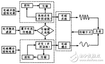
The wireless power supply system consists of a control terminal, a transmitting end, and a load rectification circuit. The electromagnetic power supply is realized by electromagnetic coupling (near-distance transmission mode) and electromagnetic resonance (long-distance transmission mode), and the system structure diagram is shown in FIG. 2 .

Figure 2 Wireless power supply system structure
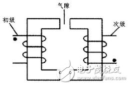
The transmitting end is mainly composed of an inverter and a transmission channel. The inverter is responsible for converting direct current (DC) to alternating current (AC), which consists of an inverter bridge, control logic and filter circuits. The short-range inverter frequency is 200~500 kHz, which is transmitted by electromagnetic coupling. The U-shaped loosely coupled ferrite core is used to isolate the wireless power supply, as shown in Figure 3.

Figure 3 short-distance transmission
The long-distance inverter frequency is 1 MHz, which is transmitted by electromagnetic resonance. The air-core magnetic resonance is used to couple the primary and secondary coils on the cylinder as the transmission medium to achieve long-distance power transmission, as shown in Fig. 4.

Figure 4 Long-distance transmission
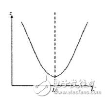
The system achieves stable and efficient transmission of electric energy through intelligent switching transmission mode. The relationship between the primary equivalent resistance and the distance in the secondary is shown in Figure 5. z is the impedance and L is the distance. Only the equivalent impedance at the position of L0 is the smallest. According to this principle, when the receiving distance is far from L0, the impedance increases, the primary current decreases, and the primary input current is collected by the Hall current sensor to judge the mode switching.

Figure 5 Secondary in the primary equivalent impedance
Portable Power Station,Jackery Battery,Portable Charging Station,Portable Power Station For Camping
Power X (Qingdao) Energy Technology Co., Ltd. , https://www.qdpowerxsolar.com