In the control application of the microcontroller, there is often a need for delay. Using assembly language, you can program a program that can precisely control the delay time, but the parameter calculation is more complicated. The calculation of the delay parameter is a problem that makes the professional feel a headache.
In order to meet the needs of the work, professionals generally have procedures to meet the needs of different delays. But for beginners, it is a more difficult problem. With the powerful simulation debugging function of WAVE3.2 integrated debugging software, it is easy to program accurate delay programs by repeating the delay parameters several times, even for beginners. The following is an example to introduce this method of programming an accurate delay program.
Programming and debugging of 10ms precise delay program
1. Basic programmingThe delay time of the delay program is mainly related to two factors, one is the frequency of the crystal used, and the other is the number of cycles in the delay program. After the crystal is determined, it is mainly how to design and calculate the number of delay cycles to be given. For example, if the crystal oscillator frequency is 6.000MHz, the maximum delay time that can be achieved by the single loop program is 255 & TImes; 2 & TImes; 2μs ≈ 1ms without the influence of subroutine call and subroutine return; the double loop program can achieve The maximum delay time is 255 & TImes; 255 & TImes; 2μs = 130.05ms; the maximum delay time that the triple loop program can achieve is 255 × 255 × 255 × 2μs = 3.316275s. Therefore, to implement a program with a delay of 10ms, a double loop program is required, and the number of loops required by the second loop program is approximately: AT=10ms/1ms=10 (times). Therefore, the basic procedure for the 10ms delay is as follows:
DELY10ms: MOVR0, #255;
The number of cycles is loaded into R0
LOOP2: MOVR1, #10; second weight
The number of cycles is loaded into R1
LOP1: DJNZR0, LOOP1
DJNZR1. LOOP2
RET
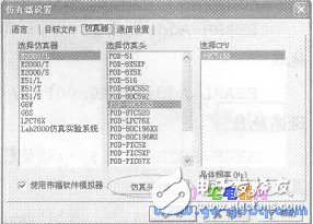
2. WAVE3.2 integrated debugging software parameter setting and delay time basic program testRun the WAVE3.2 integrated debugging software and set the “Crystal Frequency†of the “Simulation Header Setting†item in the “emulator†option of the software as shown below.

After inputting the above basic program into the newly created file and compiling it, you can test the basic program. Here are two simple test methods:
(1) The procedure for testing the program using the "execute to cursor" method is as follows:
A. Move the cursor to the "RET" command (click once to see that the cursor is flashing on this line); B. Press the “Execute to Cursor†shortcut F4 or from the menu bar “Execute/Execute to Cursorâ€.
(2) The procedure for testing the program using the "set breakpoint" method is as follows:
A. Move the cursor to the “RET†command, press the “breakpoint/cancel breakpoint†shortcut CTRl+F8 or from the menu bar “Execute/Set/Cancel Breakpoint†to set the breakpoint (the screen is set as shown below) ;B. Press the shortcut key Ctrl+F9 at full speed or from the menu bar "Execute / Full Speed ​​Execution".
By the operation of any of the above methods, the program running to the "RET" line will automatically stop. You can see the execution result shown in Figure 3. The execution time of this program is 10262.0μs in the "Execution Time" window at the bottom of the WAVE3.2 integrated debugging software window.
GALOCE bridge type Load Cell also called Double Ended Shear Beam Load Cell with steel ball centre positioning design. 10Ton,30Ton,50Ton capacity are hot sales still. They have high accuracy and side load tolerance, stable performance, and are used for electronic truck scale, rail scale, ground scale and other weighing system.
Weight Bridge Load Cell,Load Cell Transmitter,Weighbridge Load Cell,Truck scale Load Cell
GALOCE (XI'AN) M&C TECHNOLOGY CO., LTD. , https://www.galoce-meas.com