Summary:
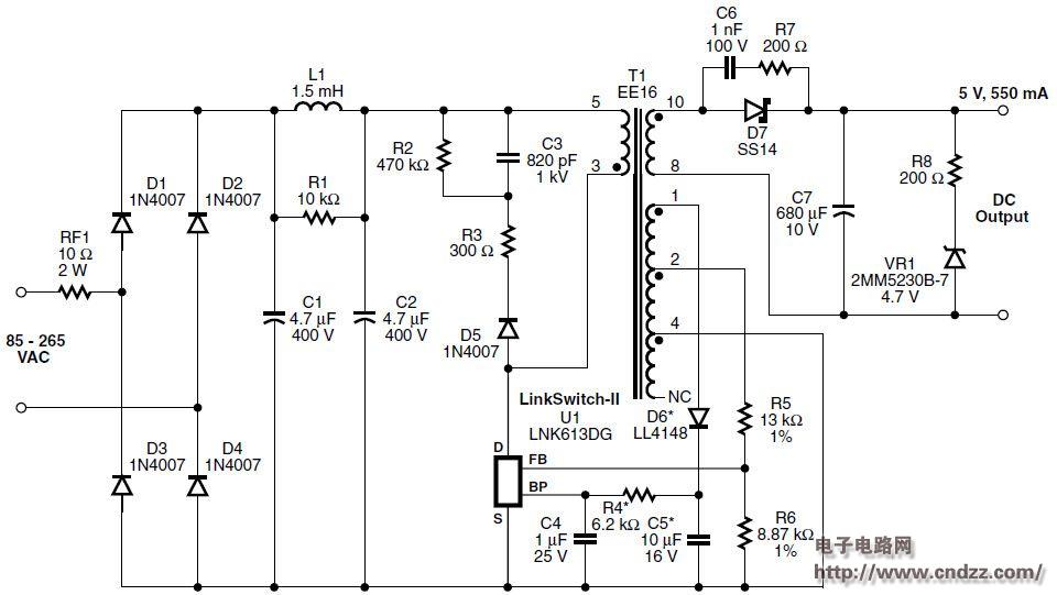
2.75W constant voltage / constant current (CV / CC) universal input charger power supply circuit diagram, the design uses Power Integrations LinkSwitch series product LNK613DG. This design is ideal for mobile phone or similar USB Charger applications, including mobile phone battery chargers, USB chargers or any application with constant voltage/constant current characteristics.
design feature
- A revolutionary control concept that enables a low component count and low cost solution
- Primary side control eliminates secondary side controllers and optocouplers
- Constant pressure (CV) accuracy: ± 5%
- Constant current (CC) accuracy: ±10%
- Overheat protection with hysteresis recovery ensures PCB temperature is safe under all conditions
- Automatic restart: output short circuit and open loop protection
- Extremely energy efficient
- Average efficiency over the entire load range: 74% (Energy Star 2.0 requires 64%)
- No-load input energy consumption: less than 40 mW at 230 VAC input
- Easily meet the following standard requirements:
- Class B Conducted EMI Requirements for EN55022 and CISPR-22 (EMI Margin >10 dBμV)
- IEC 61000-4-5 Level 3 AC Surge and ESD withstand
- Meets <5 mA battery discharge requirements
2.75W constant voltage / constant current (CV / CC) universal input charger power supply circuit diagram

See the uploading documentation for details (click to download)
Shenzhen Jinziming Electronic Technology Co.,LTD , https://www.powerchargerusb.com