Today, we will popularize the principle of PLC's jog control. This article is mainly for PLC beginners.
Figure 1:

First of all, what is jog control? Figure 2:
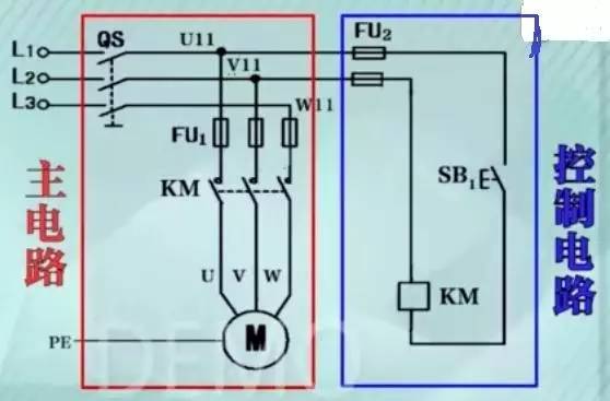
This is a traditional control circuit. We divide this circuit into two parts: the main circuit and the control circuit.
1. The main circuit consists of QS (circuit breaker), FU (fuse), KM (contactor main contact) M (motor).
2. Control circuit (also called auxiliary circuit): It consists of FU (fuse), SB (normally open contact), and KM (contactor coil).
Figure 3:
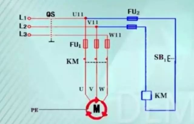
When the circuit is working, we press the button SB1, the contactor coil is energized, the armature pulls the three pairs of main contacts to close, the motor turns on the three-phase power to start the forward rotation, when we release the button, the contactor coil is broken. Electric, the motor is powered off and stops rotating. This control method is called jog control. It is mainly used for lifting and lowering of equipment, fixed-point movement control, and debugging of production equipment. In our practical application, the contactor control circuit is relatively large in volume, and long-term mechanical motion will lead to reliability of components such as buttons and contactors. Reduced, the contacts used are also limited, if we want to change the control function, then the circuit needs to be rebuilt, the workload is relatively large and error-prone, we are referring to the PLC to achieve these shortcomings, then what is the PLC? ?
Figure 4:
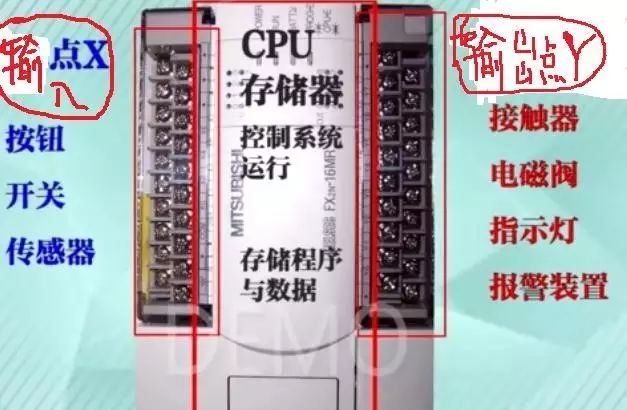
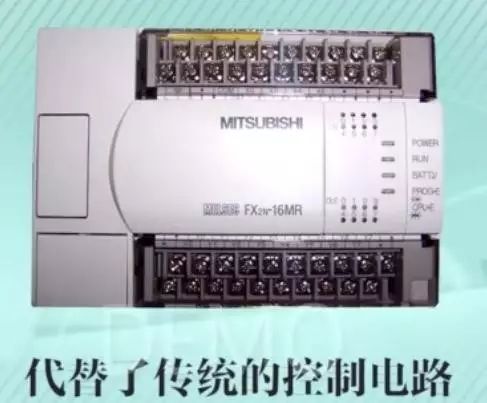
Here we take the FX2NPLC produced by Mitsubishi as an example: there are so many screws on the left that the signal input point of the PLC X is mainly suitable for input signals such as buttons, switches and sensors. On the right side, it is the output point Y of the PLC. It is used to send signals to external contactors, solenoid valves, indicator lights, alarm devices, etc., with CPU and memory in the middle, mainly to control the whole system, and to coordinate the internal system. Part of the work, as well as the function of storing programs and data. If you change the control function, you only need to modify the internal program. The external circuit does not need us to re-adjust it, so that we can debug, the hardware has fewer errors, and the use of internal relays in the PLC internal program is not limited. So how do we use PLC to realize the jog control of the motor?
Figure 5:
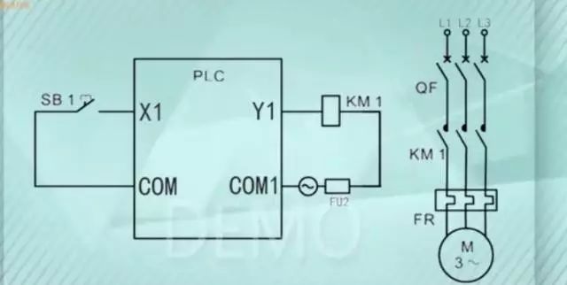
The normally open button SB1 is connected to the input point X1 of the PLC. When we press the input circuit of the SB1 button, it is turned on, and X1 gets an IO signal. The IO signal of X1 is sent to the PLC for calculation, and a signal is output. The signal Y1 turns the output loop on, the KM1 coil is energized, and the corresponding KM main contact in the main circuit is sucked.
Figure 6:
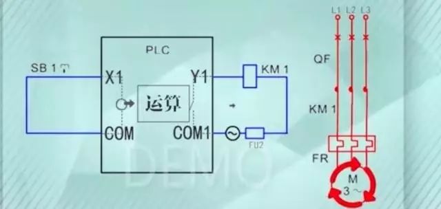
Compared with the above figure, what is the internal control operation of the PLC?
Figure 7:
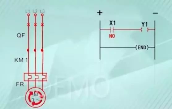
Let's see, the vertical line on the left is the left busbar, the one on the right is the right busbar, and the right busbar can be drawn or not. We assume that the busbar is connected to the positive pole of the power supply, the right busbar is connected to the negative pole of the power supply, and the input relay X1 is set to In the form of a normally open contact, the series output coil Y1, when X1 is equal to the NO state, is like the loop between the two busbars. We can think of an imaginary current flowing through the loop.
Figure 8:
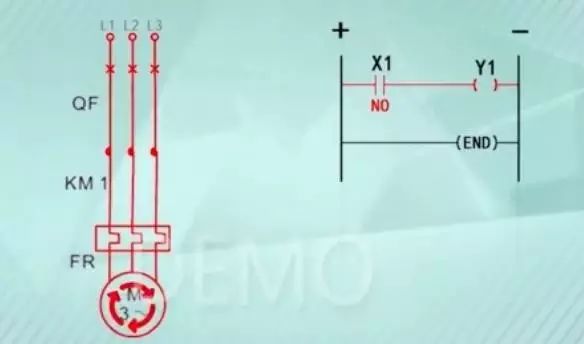
The coil has to be electrically turned on. Everyone sees that there is no red line in the upper right corner of the ladder. The corresponding Y1 contact (coil) will operate. The contactor KM1 in the main circuit will rotate forward. jobs. Have you seen? The main contact of KM1 on the left side is closed, and it becomes a straight line. At the same time, it turns red and proves that it is powered. When we release the button, we can see the following figure, as shown in Figure 9:
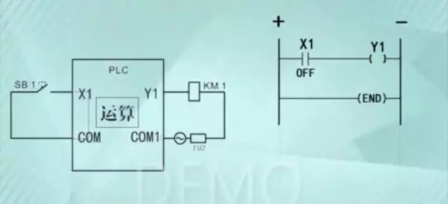
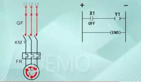
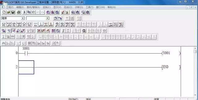
As shown above, when we release the button, that is to say, when X1 is OFF, the circuit between the busbars is open, the Y1 coil is de-energized, the main contact is reset and the motor is de-energized and stops working. The design of the jog control is completed. We call this design "Ladder", which is the internal computational control of the PLC. Finally, we use the GX simulation software to write the designed ladder diagram to the PLC. Figure 10:
Connect the external X and Y power supply circuit, press the start button, the motor starts, release the button and the motor stops working.
The electric control function is realized.
Photovoltaic Installation Tools
Pv Testers,Photovoltaic Installation Tools,Photovoltaic Tester,Solar Pv Tester
Sowell Electric CO., LTD. , https://www.sowellsolar.com