The electric track traction system was first deployed in the 19th century and is becoming more and more important in this era. Compared with diesel locomotives, this transportation mode is the best in terms of energy consumption per unit weight, and has faster acceleration and better track gradient traction performance (Figure 1).
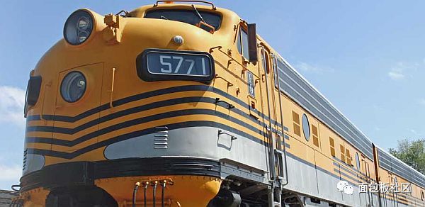
Figure 1: Electric rail traction systems require special power management solutions.
When researching the design architecture of railway power supply, I was surprised to find that so many power suppliers regard this field as a main target market. This does not include the products of IC suppliers of companies such as Siemens, and Mentor, a Siemens Business is aimed at products such as thermal reliability simulation systems for power electronics in rail traction systems.
Railway power architecture requires power
For electric railway traction power systems, the third rail and overhead wires are the main power solutions (Figure 2, Figure 3, Figure 4). The pantograph is a system that is installed on the top of the train to take electricity from the overhead tension line.
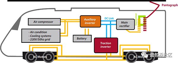
Figure 2: From the device level, IGBT power modules with air/liquid cooling (converters), inverters, rectifiers, batteries, and motors are an integral part of this system. (Picture provided by Siemens)
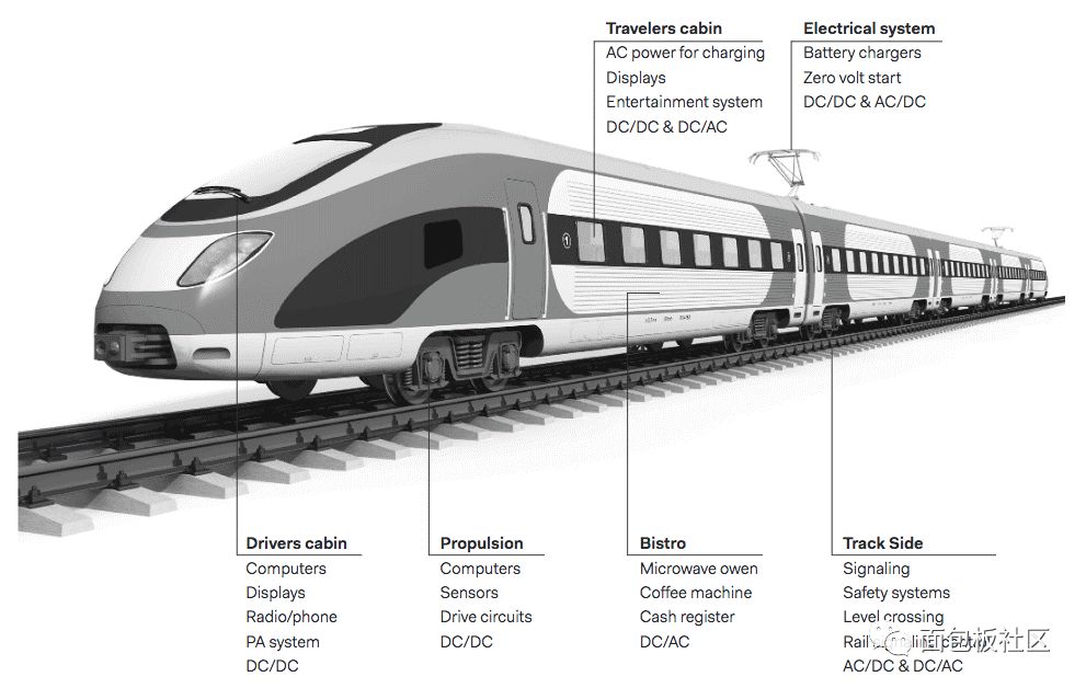
Figure 3: There are many places where power is needed in the electric track traction system. (Picture provided by Powerbox)
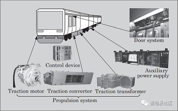
Figure 4: Types of electronic equipment for railway vehicles. (Picture provided by Fuji Electric)
challenge
Designing power converters in railway architecture has both advantages and difficulties. The main part of railway power supply design occurs in a mobile, uncontrolled environment, namely on a train. In addition, the expected service life of electric locomotives is 30 years, which means thousands of hours of service time and millions of power cycles.
There are also many places around high-speed trains that need power, such as beside the tracks. In terms of power consumption in these two parts, designers need to achieve higher than normal reliability in harsh and uncontrolled environments.
Power devices in this environment will encounter severe electrical heating conditions, such as short circuit, overvoltage, overcurrent, overheating, and aging effects. In this type of application, reliability is essential, and extreme operating temperatures are a severe test for even the most reliable devices.
The power supply is usually cooled by convection, and the operating temperature of the entire power supply system must be as low as -40°C. In these power systems, vibration-compensating spring clip terminals and conformal coatings are used, and a very lightweight design is provided in a compact form. All of these are part of the design architecture, and all architectures must also exhibit the highest efficiency. .
Some other railway standards include:
* EN 55022 Class A and Class B; * EN 61000-4-2 (ESD); * EN 61000-4-3 (RF resistance); * EN 61000-4-4 (fast transient); * EN 61000- 4-6 (anti-conduction performance); * EN 50163; * RIA 12 surge protection (3.5VN 20ms); * RIA 13 and RIA 20 mechanical standards; * IEC 571 and IEC61373 shock/vibration.
Railway applications will emphasize the high load and long life requirements of these power solutions, especially for discrete power devices such as MOSFETs, diodes, transistors and IGBTs. The technologies adopted by Siemens for this purpose include: direct bonding of copper substrates to improve heat transfer coefficient; replacement of thicker bonding wires with strip bonding to better handle large currents; and solderless top sheets with very low thermal resistance (Die-attach) technology. The above-mentioned technologies are used to increase the number of power on and off and withstand the thermal effects of the module package.
Railway applications
Signaling and applications beside tracks
Level crossing control and signaling control systems do not need to meet EN50155. Most railway applications outside the car or beside the track require an AC-DC power supply instead of a DC-DC converter.
The following is an example of a trackside application that ADM has recently helped customers implement. The customer needs to replace the power supply in the information screen of the subway station. This is due to changes in wiring regulations that require the display to be powered by DC voltage instead of 240VAC. One problem that must be overcome is to allow the voltage to drop more than 100V.
A Mean Well power supply RSP-2400-48 is used in the control cabinet far from the underground platform to convert the input 240VAC into 48VDC/50A output. A Mean Well SD-25C-5 DC-DC converter has been updated for each display screen, which is used to convert the input 48VDC to the 5VDC required for the display to supply power.
Rolling stock
Propulsion system (IGBT control, brake control, computer); • Cockpit (power display, communication system, etc.); • Passenger compartment (AC power charging, information display, entertainment system); • Dining car (microwave oven, coffee machine, Cash register, computer) → battery charging and system electricity generation; charging equipment for motor starting; • brake magnetization in traction applications; • zero-volt starting applications.
The following are examples of rolling stock applications that ADM has recently helped customers to install and configure precision clock power supplies. The company selected a Mean Well PLN-60-12 power supply to power high-precision network-controlled clocks-this type of clock is widely used on Australian railway networks. Facts have proved that PLN-60-12 is very reliable. This is important because the risk of turning on this device once it is installed is very high.
Traction converter
When electricity is used in a traction system in a railway system, we usually call it electric traction. Rail electrification refers to the type of power system used when powering electric locomotive systems. It can be AC ​​or DC, or a composite power supply (Figure 5).
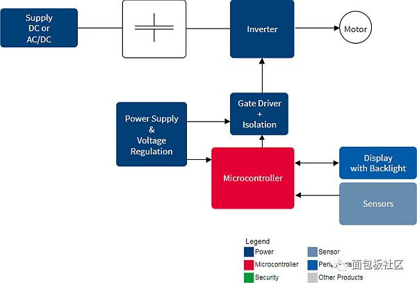
Figure 5: Infineon's IC solution for traction system design. (Picture provided by Infineon)
The choice of the type of electrification depends on many factors, such as the availability of power, the type of application, or whether it is urban, suburban, or mainline service.
There are three main types of electric traction systems:
1. Direct current (DC) electrification system (300, 500, 600, 750, 1200, 1500 and 3000VDC);
2. Alternating current (AC) electrification system (and 25kVAC@50/60Hz, see Figure 6);
3. Composite system (1.5kVDC, 3kVDC, 25kVAC@50Hz).
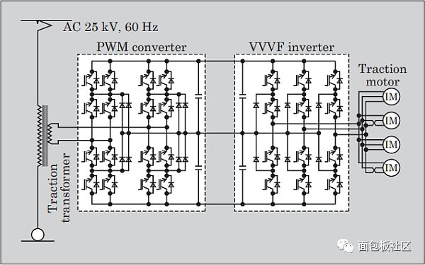
Figure 6: Shown here is an AC design with a three-level pulse width modulation (PWM) converter and a variable voltage and variable frequency (VVVF) control system inverter architecture. The design uses a single 3-level VVVF inverter to jointly drive four traction motors in parallel. (Picture provided by Fuji Electric)
Auxiliary power
The main DC voltage fed to the DC electric rail train system is 1,500VDC, 750VDC or 600VDC. The IGBTs used in these designs use a two-stage converter design architecture (Figure 7).
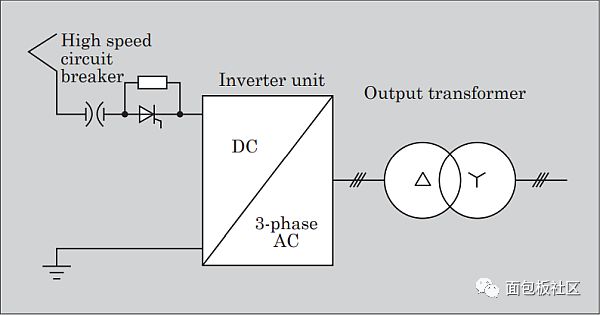
Figure 7: Design of auxiliary power supply circuit for DC electric rail vehicles. (Picture provided by Fuji Electric)
The auxiliary power loads on AC electric railcars are usually indicator lights, internal lighting and control power, and the capacity is relatively small, however, reliability is critical (Figure 8).
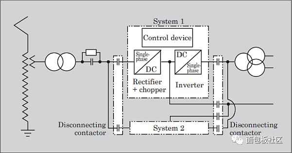
Figure 8: Design of auxiliary power supply circuit for AC electric rail vehicles. (Picture provided by Fuji Electric)
Sometimes the auxiliary power supply is installed on the top of the electric rail car (Figure 9).
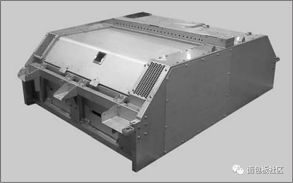
Figure 9: Auxiliary power supply mounted on top. (Picture provided by Fuji Electric)
Electric door system
In older designs, pneumatic door systems are often used in Japan and elsewhere. However, the electric door system has recently become the designer’s first choice because it does not require much maintenance, and when passengers or luggage are in danger of being caught by the door, the use of self-diagnostics and high-speed control response systems can also improve Passenger safety (Figure 10).
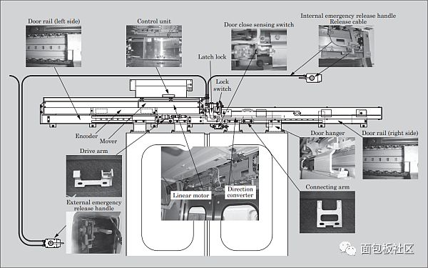
Figure 10: Electric door system. (Picture provided by Fuji Electric)
IC solution
Siemens
Siemens claims that if there is no power converter, electric rail traction chain (ERTC) is impossible. These power devices transfer and switch current to different branches of the power converter, and have high current and high voltage capabilities.
Siemens provides power solutions for Germany's newest train-ICE 4 (BR 412) high-speed train. Their components and system solutions cover mechanical and electrical requirements, as well as system solutions for propulsion systems, bogies (a railway driving and guidance system, see Figure 11), and on-board power supplies.
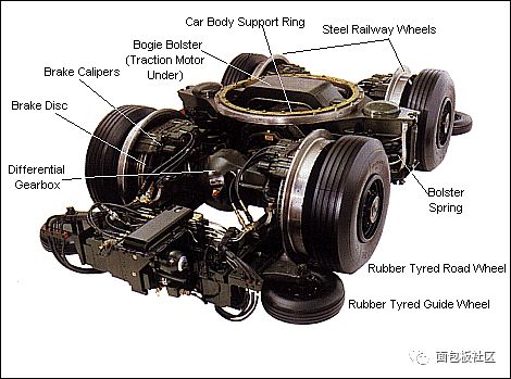
Figure 11: A bogie is a four-wheel or six-wheel steering vehicle that provides support for the body and is used to provide traction and braking force. (Picture provided by Railway Technical website)
Power module solution
Vicor
I had a conversation with Kai Johnstad, Senior Product Marketing Manager of ChiP DCM IC at Vicor. These modules can work under a wide range of unregulated inputs and produce isolated DC outputs. Railways have some unique requirements, and Vicor has been customizing its own railway solutions to meet these requirements for two decades (Figure 12).
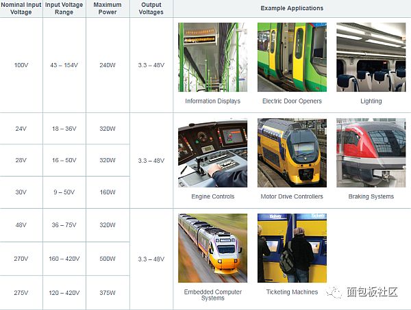
Figure 12: Vicor's DCM IC for railway applications. (Picture provided by Vicor)
DCM IC has a high-frequency zero voltage switching (ZVS) topology, and the converter can provide high efficiency over its entire input voltage range. These DC-DC converter modules (DCM) can meet the needs of rail applications, especially the 100VIN3623 ChiP with a wide input voltage range of 43-154V, which can be applied to rail applications with a rated voltage of 72 or 110V. These power solutions can provide power conversion for various systems, from embedded computer systems to information displays. The efficiency of this new series of products is close to 93%, and the power density is as high as 653W/in3, allowing engineers to use a small volume regulated DC-DC converter to achieve a variety of nominal input voltages used by rail power designers.
Vicor showed designers how to use modular DC-DC converters to meet European railway application standards.
Schaefer
Schaefer's railway-grade power conversion products include AC-DC power supplies, DC-DC power converters, rectifiers and battery chargers, and DC-AC sine wave inverters. They specialize in providing customized railway power solutions for on-board and trackside heavy rail power applications, and comply with EN 50155 standard requirements.
For the railway industry, ensuring the provision of a stable power system presents considerable challenges because not only have strict technical and performance requirements, but also need to comply with several international standards.
The following are some of the needs of this industry:
• Ultra-wide input range to handle extreme situations, such as 74VDC
The railway power supply provided by Schaeffer for train battery chargers includes a 4.5kW on-board battery charger system and a 40kW AC/DC on-board battery charging system.
Absopulse
Typical applications of Absopulse railway converters include:
Signaling and communication system; •Wireless connection solution; •GPS tracking system; •Video surveillance and security system; •Passenger information display system; •Customer entertainment system; •Train control and monitoring system; •Traction control system; •Gate control System; • Headlight and taillight system.
Some typical products provided by Absopulse include 750VDC railway DC/DC converters suitable for public transportation, and IP66-rated railway DC/AC pure sine wave inverters with a wide input range.
XP Power
XP Power has launched a new type of railway power supply-RDF50/RDL100/RDH300/RDH600 series for high-efficiency 50W to 600W DC/DC converter series for railway applications.
XP Power pointed out that the following requirements should be considered when choosing a power supplier:
1. Comply with unified standards such as EN50121, EN50124, EN50125, EN50155 and EN50163, as well as national standards such as RIA, NF-F-01-510, VDE, ST;
2. The reliability of conservative components after derating;
3. Comprehensive design verification test (DVT);
4. Long product life cycle and end of production (EOL) management;
5. Special project management;
6. Wide input voltage, suitable for DC battery input voltage commonly used in the world;
7. EMC/EMI control and anti-peak and surge performance;
8. Rugged construction standards;
9. Wide operating temperature range (typical value -40℃ to 70℃);
10. Convection or conduction cooling;
11. Parallel and redundant operation;
12. Overheating, overvoltage, and overcurrent protection;
13. Comply with RoHS;
14. ISO9001 quality management system.
Power control system
Railway Technology is their representative of a series of new power control system products, including multi-output DC-DC converter MD146-IRX-2-N1 for railway signaling power supply equipment (PSU), and subway signaling equipment The DC-DC converter RACK-4XSD206-I-RX-96-1.
One challenge is that many remote areas have no electricity supply.
Other suppliers of railway power module converters include companies such as Synqor, PULS, Toshiba and Bel Power.
Custom and standard railway design
Powerbox has completed many excellent standard railway power supply designs, but also provides custom designs for railway applications (Figure 13).
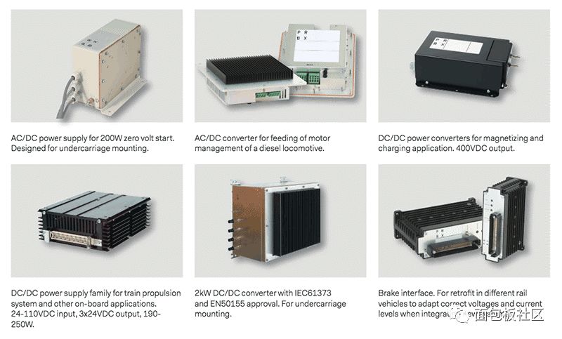
Figure 13: Some examples of Powerbox power products used in railway systems. (Picture provided by Powerbox)
Examples of customer power requirements
1. Redesign the propulsion system
Challenge: The problem started with an emergency call from a customer. In the first test of a complete new car, the propulsion system will randomly stop, initially suspected to be the cause of the Powerbox DC/DC converter.
Solution: The Powerbox investigation team conducted actual tests and measurements on site the next day, as well as theoretical analysis. It turns out that the problem lies in a subsystem powered by the converter. In some operating modes, this subsystem can cause severe overload of the converter, far exceeding the design parameters. The team proposed a solution that is to redesign the subsystem. The plan has been implemented and the project is proceeding as planned.
2. System solution to solve the problem of noise and transient exceeding the requirements of EN50155/EN50121-3-2
Challenge: An old customer of Powerbox encountered a problem during locomotive modification. The battery charger input circuit failed repeatedly. After identification, the cause comes from the combined effect of the noise caused by parallel equipment and the transient caused by the bounce of the pantograph (carrying current from the overhead wire to the joint frame of the train). Noise and transient levels far exceed the limits required by EN50155 and EN50121-3-2 standards, and exceed the range that battery chargers can handle. Customers know that Powerbox is a railway power supply expert, so they turn to them to provide possible solutions to this problem.
Solution: The customer and Powerbox jointly decide that filtering is the most convenient way of processing. Within three weeks, Powerbox engineers designed and manufactured an external low-pass filter to reduce noise and transients to the recommended level, thereby protecting the charger.
3. From converter requirements to system optimization
Challenge: The task proposed by the customer is to power signaling equipment on a large number of remote trackside facilities. The input voltage provided is AC mains power, and the required output depends on the equipment requirements of each site and is a variety of DC voltages. In addition, a spare battery is required. Since most equipment is installed in cabinets with limited thermal management capabilities, minimizing heat dissipation is essential. A large number of remote sites means that reliability is an essential prerequisite, which requires a short mean time to recovery (MTTR).
Solution: Powerbox was originally invited to provide a DC/DC converter for this application. But when they analyzed the application scenarios, they found that the application of lean design and modular concepts can save a lot of costs in several other areas. The customer agreed with their suggestion, and the initial DC/DC converter invitation became a customized system order. Powerbox has designed a modular power system, which integrates power conversion, battery charging, power distribution boards and computer communication interfaces. High-efficiency converters and intelligent system architecture also greatly reduce heat dissipation.
Mccb Breaker,Mccb Circuit Breaker,Overload Protection Mccb,Moulded Case Circuit Breaker
ZHEJIANG QIANNA ELECTRIC CO.,LTD , https://www.traner-elec.com