Timer/counter structure (T0 and T1)
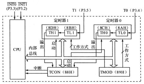
The difference between timers:
T0 can be divided into 2 independent 8-bit timers, while Timer 1 cannot;
T1 can be used as a serial port baud rate generator, but Timer 0 cannot.
working principle
Timer: The pulse source is provided by the system's clock crystal oscillator output pulse source
Counter: The pulse source is provided by an external pulse source input from the T0 or T1 pin (P3.4 or P3.5)
Purpose: timers and counters
Core: plus 1 counter
Principle: Every time a pulse comes, the counter is incremented by 1, and when all 1s are added, another pulse is applied to reset the increment counter to zero. At the same time, the overflow of the increment counter causes the TF0 (or TF1) in the TCON register to be set to 1, to the CPU Issue an interrupt request
Pulse source:
Note: neither T0 nor T1 can be used as both a timer and a counter at the same time
supplement:
The working principle of the counter:
When used as a counter, count the external pulses of the T0 or T1 pin. If the sampled value of the previous machine cycle is 1 and the sampled value of the next machine cycle is 0, it means that there is a pulse and the counter is incremented by 1.
The input level of the pin is sampled during S5P2 of each machine cycle. The new initial value of the count is loaded into the counter during S3P1 of the next machine cycle.
This method requires two machine cycles to detect a 1->0 negative transition signal, so the highest counting frequency is 1/24 of the clock frequency.
S5P2:
S5P2 refers to phase 2 of the 5th clock cycle.
The oscillation signal of the crystal oscillator is input from the XTAL2 terminal to the on-chip clock generator. The clock generator is a two-frequency flip-flop circuit, which divides the signal frequency of the oscillator by 2, and provides a two-phase clock signal to the CPU. P1 and P2. The period of the clock signal is called the machine state time S, which is twice the oscillation period. In the first half of each clock cycle (that is, the machine state time S), phase 1 (that is, the P1 signal) is valid, and in the second half of each clock cycle, phase 2 (that is, the P2 signal) is valid.
Register used
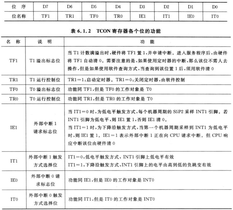

TCON control register: start and stop the counting of the timer/counter, and control the working status of the timer, it cannot be addressed by bit
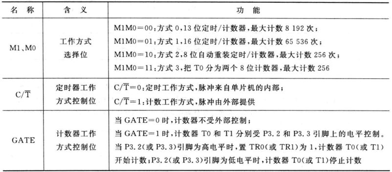
TMOD mode register: Set the working mode of the timer, select the function of timing or counting, and can be addressed by bit. (Shared registers with interrupts, the upper four bits are used for timer counters, and the lower four bits are used for interrupts)
Note: The logical structure of GATE is skipped here
Way of working:
Way 0
Calculation formula:
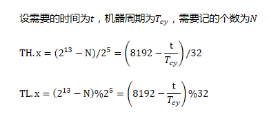
Maximum count: 8192 machine cycles
Working principle: 13-bit counter, composed of the lower 5 bits of TL0 and the upper 8 bits of TH0. When the lower 5 bits of TL0 overflow, it will carry over to TH0. An interrupt request is issued when TH0 overflows.
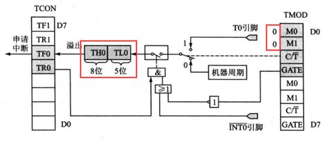
Way 1
Calculation formula:
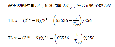
Maximum count: 65536 machine cycles
Working principle: 16-bit counter, TL0 as the lower 8 bits, and TH0 as the upper 8 bits
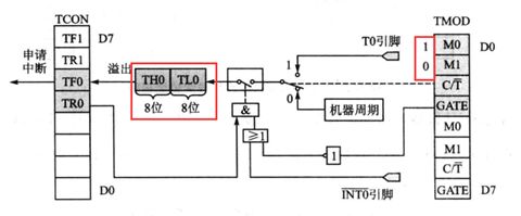
Method 2: 8-digit counting method with automatic reloading of initial value
Calculation formula: ps crystal oscillator frequency must be an integer multiple of 12, because the frequency of the timer is 1/12 of the crystal oscillator frequency.
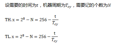
Maximum count: 256 machine cycles
Advantages: suitable for more accurate pulse signal generator
Disadvantages:

Working principle: After the counter overflows, the counter will automatically reload the initial value set last time.

Mode 3: ps can only be used for timer/counter T0. When T0 works in mode 3, T1 should not be used in interrupted occasions. Usually T1 is used as a serial port baud rate generator in this case
Working principle: Divide T0 into two independent 8-bit timer/counters TL0 and TH0.
TL0 is a normal 8-bit timer/counter. After the counter overflows, TF0 is set to apply for an interrupt, and then the initial value is reinstalled.
TH0 is also an 8-bit timer/counter, but because TL0 occupies TF0 and TR0, TH0 occupies timers TF1 and TR1 (so T1 cannot be used)

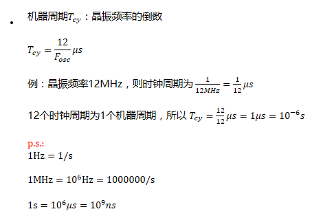
Clock cycle/machine cycle calculation:
Timer/counter initialization
Assign value to TMOD to determine the working mode of T0 and T1
Calculate the initial value and write it into TH.x and TL.x
Use interrupt mode to assign value to IE register to develop interrupt
Set TR0 or TR1 to start the timer/counter
Guangzhou Lufeng Electronic Technology Co. , Ltd. , https://www.lufengelectronics.com