1. Composition and function of CAN bus
1. The composition of CAN data transmission bus system
Take Mazda 6 automobile as an example to introduce the structure and principle of CAN bus system.
The Mazda CAN data transmission bus system consists of 1 CAN controller and 1 transceiver inside each control unit (for example, ABS, PCM, BCM, etc. control units), and 2 CAN data buses connected externally to each control unit. The two terminals in the whole system are composed as shown in Figure 1.
2. The advantages of CAN system control circuit and traditional module control circuit
CAN system related modules are composed of circuit, CPU and input/output interface, which eliminates the excessively large input/output interface in traditional electrical modules. The small module size simplifies the wiring harness of the entire vehicle and improves the working reliability of the electrical circuit of the entire vehicle.
2. FAW Mazda M6 car CAN bus system
The CAN bus system of FAW Mazda M6 (MAZDA6) car is shown in Figure 3, which is used to transmit multiple input/output signals between various electrical modules.
The main transmission line of the CAN bus of the FAW Mazda M6 car is connected to the anti-lock braking system (ABS) or ABS/TCS (ABS system with traction control), DSCHU/CM (power stability control), PCM (power control module) , Diagnostic connector, combination instrument and sound system. The transmission lines are all connected by twisted pair wires. Through the self-diagnosis function of this bus, using the fault diagnosis instrument SST (WDS or similar instrument), various codes DTC stored in the system can be displayed, so that the maintainability of the system can be greatly improved.
Each system node module (control unit) connected to the CAN bus is composed of CAN controller, CAN transceiver, microprocessor (CPU) and I/O (input/output) interface and other circuits. The microprocessor (CPU) controls the data exchanged on the CAN bus and sends it to all modules of the CAN related system. However, only when the relevant module receives the signal, the corresponding instruction (such as lighting the indicator light, etc.) is executed, and the signal received by other modules will be ignored.
Three, Toyota car series CAN bus system circuit diagram
Take Toyota Kaimei car as an example to explain the reading of CAN general route system circuit diagram.
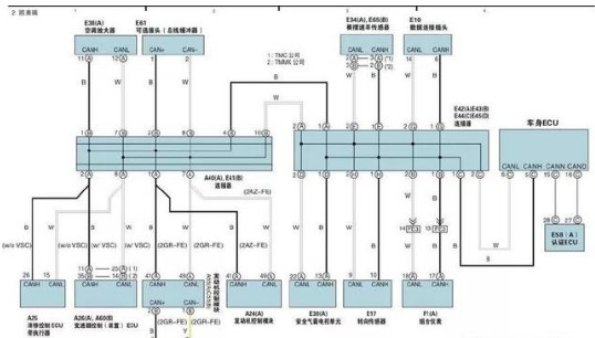
Figure 4 shows the Toyota Camry CAN total route system circuit. CAN uses two wires CANH and CANL to provide the operating voltage for communication. CAN has high-speed transmission performance and the ability to detect errors.

Figure 4-CAN bus circuit diagram of Toyota Camry
Engine ECU A55 (A) [or A24 (A)] is connected to the A1 and A7 terminals of the connector A40 (A); the automatic transmission ECU is connected to the engine ECUA 55 (A) through the CAN line, and the yaw rate sensor is connected to the connector E42 (A) ) Terminals E1 and E2; sliding ECU A25 with actuator [or A26] connect to terminals A2 and A8 of connector A40 (A); connect air-conditioning amplifier to terminals B1 and B7 of connector A40 (A); connector A40 ( A) The B2 and B8 terminals of A) are connected with optional connectors E61 as bus buffers; the airbag electronic control unit E30 (A) is connected to the D1 and D2 terminals of the connector E42 (A); the steering sensor is connected to the connector E42 (A) The H1 and H2 terminals of the combination meter are connected to the B1 and B2 terminals of the connector E42 (A); the G1 and G2 terminals of the connector E42 (A) are connected to the data connection plug; the certification ECU is connected to the C15 and C16 terminals of the body ECU, and the body ECU is connected to the C1 and C2 terminals of the connector E42 (A).
The stadium LED screen is ideal for places of with huge crowd. Its high resolution picture and wide viewing angle ensure best quality pictures and videos to every corner of the stadium. Stable body protects the display from any damage, even high speed ball.
The LED Display is manufactured by using best quality material, purchased from most reputed vendors. The final products feature supreme quality and offers best outputs. High refresh rate and gray scale ensures the picture quality remains seamless.
The display features a wide viewing angle of 120° horizontal and 120° in vertical which reaches more viewers. The picture quality remains seamless in all direction and at a distance, presenting all viewers the same highly quality outputs. This makes it suitable for large gathering. -
Stadium LED Display,Football Led Display,Staduim Led Display,Outdoor Football Led Display
Guangzhou Chengwen Photoelectric Technology co.,ltd , https://www.cwledpanel.com