In 1888, the Austrian plant botanist Leinitzl discovered liquid crystal, which is a strange organic compound with two melting points. When the solid crystal is heated to 145℃, it melts into a liquid, but it is turbid. , And all pure substances are transparent when melted. If you continue to heat to 175°C, it seems to melt again and become a clear and transparent liquid. Later, the German physicist Lehmann used his personal design to observe these lipid compounds as the latest polarizing microscope with a heating device. He discovered that although this kind of white and turbid liquid is liquid in appearance, it shows the birefringence characteristic of anisotropic crystals. So Lehmann named it "liquid crystal", which is the origin of the name "liquid crystal". Lenize and Lehman were later known as the fathers of liquid crystals. Since the discovery of liquid crystal, people didn't know what it was used for. It wasn't until 1968 that people used it as a material in the electronics industry.
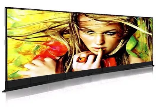
Since the birth of the first LCD display in 1968, the technological development of LCD has gone through 5 stages:
The first stage (1968-1972)
In 1968, the American RCA company developed a dynamic scattering type liquid crystal display. In 1972, it produced a dynamic scattering type liquid crystal watch. LCD technology has since moved to the practical stage.
The second stage (1971-1984)
In 1971, the Swiss inventor of the twisted nematic (TN) liquid crystal display was industrialized by Japanese manufacturers. Due to the low manufacturing cost of TN-LCD, it became the mainstream of liquid crystal products in the 1970s and 1980s.
The third stage (1985-1990)
After 1985, due to the development of Super Twisted (STN) liquid crystal displays and the invention of amorphous silicon thin film transistor liquid crystal display technology, the development of LCD technology has entered the stage of large-capacity display.
The fourth stage (1990-1995)
Based on the rapid development of active matrix liquid crystal displays, LCD technology has begun to enter the stage of high-quality liquid crystal displays.
The fifth stage (after 1996)
LCD has been widely used in notebook computers. Since 1998, TFT-LCD products have entered the monitor market. The three major problems that have long plagued liquid crystals have been basically solved for viewing angle, color saturation and brightness.
Liquid crystal and its classification
The material form that has the fluidity of a liquid mechanically and a crystalline property optically is named as flowing crystal-liquid crystal.
Liquid crystals are divided into two categories: lyotropic liquid crystals and thermotropic liquid crystals; liquid crystals used as display technology are all thermotropic liquid crystals.
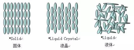
When the temperature is lower than T1, it becomes a solid (crystal). T1 is called the melting point of the liquid crystal. When the temperature is higher than T2, it becomes a clear, transparent and isotropic liquid state. T2 is called the clear point of the liquid crystal. The operating limit temperature range of LCD is basically determined by T1 and T2.
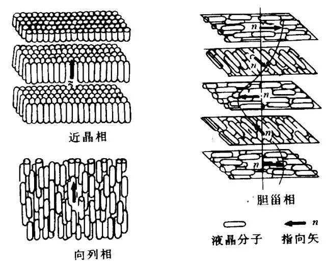
The smectic liquid crystal molecules are two-dimensionally ordered. The molecules are arranged in layers. The long axes of the molecules in the layer are parallel to each other and arranged neatly. The center of gravity is in the same plane. The direction can be perpendicular to the plane or arranged at an angle to the plane. The thickness of the layer Equal to the length of the molecule, the distance between the layers can be changed. The molecule can only slide back and forth, left and right within the layer, but cannot move between the upper and lower layers. The viscosity and surface tension of smectic liquid crystals are relatively large, and they are not sensitive to changes in external electricity, magnetism, and temperature.
Nematic liquid crystal molecules have only one-dimensional order. The long axes of the molecules are parallel to each other, but they are not arranged in layers. They can slide up and down, left and right, and back and forth. They only stay parallel or nearly parallel to each other in the direction of the long axis of the molecules. The interaction is weak, the arrangement and movement of nematic liquid crystal molecules are relatively free, and they are more sensitive to external electricity, magnetic field, temperature, and stress. They are currently the main material of display devices.
Cholesteric liquid crystal is a liquid crystal derived from cholesterol. The molecules are arranged in layers, the molecules in the layer are parallel to each other, and the long axis of the molecule is parallel to the plane of the layer. The direction of the long axis of the molecule in different layers changes slightly. The long axis has a slight twist angle (about 15 minutes) to each other. The layers are twisted into a spiral. The distance between the layers of 360º rotation is called the pitch, which is roughly equivalent to the wavelength of visible light. The cholesteric phase is actually a kind of distortion state of the nematic phase, because the long axes of the molecules in the cholesteric layer are also oriented parallel to each other. It is just that the preferred orientation rotates at a fixed angle from one layer to another. Stacked to form a spirally arranged structure, adding racemic nematic liquid crystal to the cholesteric phase or mixing the right and left cholesteric phases in an appropriate ratio can transform the cholesteric phase into a nematic phase. A certain intensity of electric and magnetic fields can also transform cholesteric liquid crystals into nematic liquid crystals. The cholesteric phase is easily affected by external forces, and is particularly sensitive to temperature. Temperature can cause the pitch to change, and the wavelength of its reflected light is related to the pitch. Therefore, the cholesteric liquid crystal changes its color with heat and cold.
The basic structure and imaging principle of LCD liquid crystal display
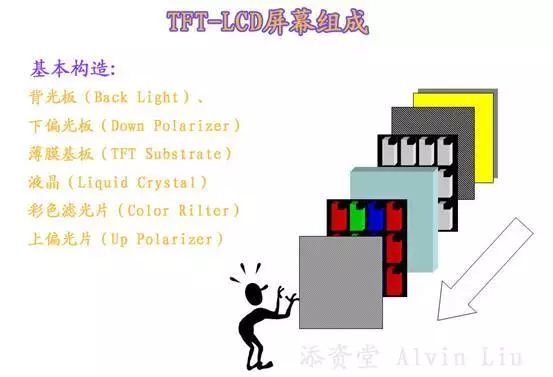
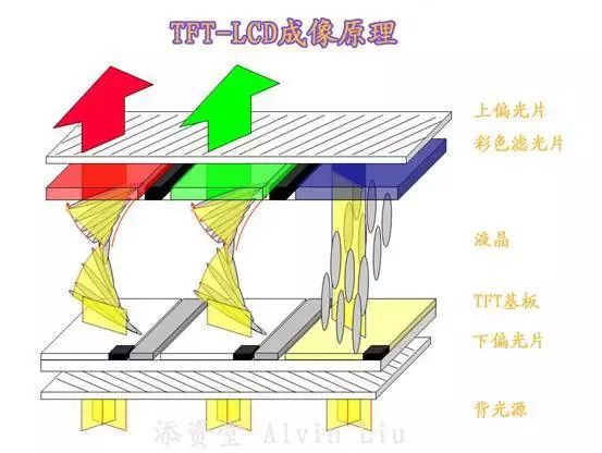
1. Backlight board: The imaging principle of LCD is to control the brightness and darkness by blocking the light component of the liquid crystal. Therefore, a light source is necessary to see the image on the screen. Therefore, the backlight board is responsible for providing the most basic light source for LCD display.
2. Lower polarizing plate: the direction of the light from the backlight plate is inconsistent and radial. If such light passes through the twisting of the liquid crystal molecules, we still cannot see the normal image on the screen, and what we see may be white. , Or colorful patches of color, but not the image we want to see. The following polarizer is responsible for the work of regulating the direction of light to the same before sending it to the liquid crystal layer.
3. Film substrate: the twist angle of liquid crystal molecules is controlled by TFT.
4. Liquid crystal: This layer of liquid crystal molecules are twisted under the control of TFT to control the brightness of the light in the same direction, so that the brightness of the light to the rear pixel unit is changed.
5. Color filter: If you are lucky enough to remember about the 1980s, I believe you will remember that there was often a colored plastic sheet in front of the black and white TV screen at that time. After installing this plastic sheet, the black and white TV set It seems that it has become a color TV. We can see that sometimes people's faces turn pink, lips turn red, and other scenes are colored, although sometimes the colors are not realistic. In fact, this piece of plastic is a color filter.
The liquid crystal itself has no color, so color filters are used to produce various colors. The color displayed by each liquid crystal sub-pixel in the LCD screen depends on the color filter, not the sub-pixel. The backlight emits white light, and the white light passes through each After the color filter of different colors, we can see behind the color filter that the light of the color corresponding to the color filter is transmitted, so in the LCD display, the function of the color filter is to color, and the CRT monitor Correspondence with phosphor function. Liquid crystal sub-pixels can only adjust the gray scale by controlling the intensity of light passing through. Only a few active matrix displays adopt analog signal control, and most adopt digital signal control technology. Most digitally controlled LCDs use an 8-bit controller (some digital controls use a 10-bit controller), which can generate 256 gray levels. Each sub-pixel can express 256 levels, then you can get 256×3 colors, and each pixel can express 16,777,216 colors, which is what we commonly call 16,777,216 colors. Because the human eye's perception of brightness does not change linearly, and the human eye is more sensitive to changes in low brightness, this 24-bit chromaticity can fully meet the ideal requirements. Engineers used pulse voltage adjustment to make the color changes look more uniform.
6. Upper polarizing plate: The original direction of the light becomes inconsistent after being twisted by the liquid crystal layer. Therefore, if the diffused light is not re-regulated, what you see in front of the screen will still be white. The light that has been twisted by the liquid crystal is not reflected, so the diffused light must be regularized here. A polarizer that is orthogonal to the polarization direction of the lower polarizer is used to re-deflect the optical center that has been twisted by the liquid crystal. The brightness of the polarizing plate is different, so we can see the alternating light and dark pictures on the screen, because the deflected light is the colored light that has passed the color filter, so we can see the image we need in front of the screen.
No upper polarizer
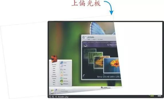
Comparison of the effect of upper polarizer and no upper polarizer
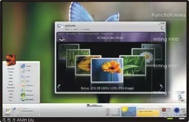
Plus the complete picture of the polarizer
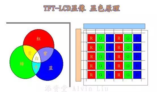
The color imaging principle of LCD is the same as that of CRT, and various colors are composed of three primary colors of red, green, and blue. The difference is that the CRT generates colored light by hitting the three primary colors of phosphors by high-speed electron beams, and the LCD generates colors after regularly coated with three primary colors of color filters. By controlling the liquid crystal molecules under each primary color of the color filter to change the brightness of the light passing through the liquid crystal molecules, the primary colors with different brightness can simulate various colors in nature. Since the color filter is under the upper polarizing plate, the viewing angle of the image on the LCD screen is required, but this problem has now been solved quite well.
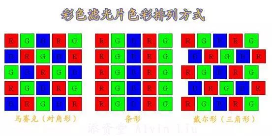
We know that the primary color arrangement of color filters is different. Depending on the position of the color filter's primary color, the control sequence of the corresponding liquid crystal molecule unit must be changed accordingly, otherwise the displayed image can only be a blurred screen.
The stripe arrangement of the three color filter primary color arrangements in the above figure is the simplest. Because the primary color arrangement is simple vertical and horizontal lines, it is relatively simple to control, but the image obtained by this arrangement order is not perfect. It may appear that the displayed line thickness is uneven, and the slanted line surface of the image is severely jagged. Therefore, a mosaic arrangement of green sheets has been developed. This arrangement can better solve the image jagged problem, but this arrangement sequence still cannot solve the problem of fine line display. The image lines obtained by this arrangement may sometimes be normal, but there are Sometimes the thickness is different, so the Dell-shaped arrangement of color filters is produced. This arrangement can solve the problem of jaggedness and uniform line thickness. However, the control of the liquid crystal molecules of this arrangement is the most complicated.
The main working mode of LCD
A variety of working modes are derived from the basic principles of liquid crystal display, mainly including: TN mode, STN mode, FLC mode, and liquid crystal-polymer mode. At present, twisted nematic liquid crystal (TN) is about to be phased out, and super twisted nematic (STN) and active matrix (TFT) are mature and popular.
Twisted nematic (TN) liquid crystal display
Twisted nematic (TN is the abbreviation of Twisted Nematic in English) liquid crystal is a nematic liquid crystal with a 90º twist. Twisted nematic liquid crystal displays appeared in the 1970s. In addition to the basic characteristics required for liquid crystal displays, they also have the characteristics of high contrast, simple manufacturing technology, and low cost. At present, this type of liquid crystal display is mostly used in portable calculators, clocks, and instruments. At present, most domestic LCD manufacturers produce such products.
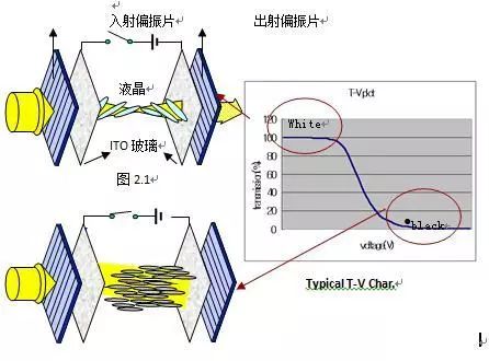
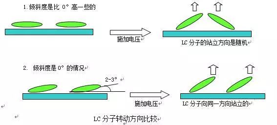
A twisted nematic (TN) liquid crystal display is formed by sandwiching a twisted nematic (TN) liquid crystal material between two ITO glass plates. The thickness of the liquid crystal is generally 5 µm, and its specific thickness is related to the birefringence of the liquid crystal material. The upper and lower ITO glass substrates are coated with a layer of alignment layer, using the interaction force between the liquid crystal molecules and the surface of the alignment layer, using the rubbing of the liquid crystal molecules and the surface to align in parallel with the tilt angle of 2-3º as shown in the figure. The upper and lower substrates are rubbed in the direction of 90º, which makes the liquid crystal molecules twisted to 90º. At the same time, a small amount of chiral material is mixed into the liquid crystal to determine the twisting direction of the liquid crystal molecules. Polarizers are attached to the outer sides of the upper and lower glass substrates, and the optical axis of the polarizers is consistent with the rubbing direction of the glass substrates, thereby obtaining a normally white display on the liquid crystal display. When the polarization plane of the incident light rotates 90º with the liquid crystal molecules, the polarized light passes through the polarizer to obtain a bright state. When a voltage is applied, the positive liquid crystal molecules are aligned with the direction of the electric field, and the polarization plane of linearly polarized light remains unchanged, and the polarized light cannot pass through the polarizer on the side of the emitted light to obtain a dark state, so the liquid crystal display is an electrically controlled light valve. However, due to the fact that the twisted nematic (TN) liquid crystal display is currently under optimized parameters, its maximum scan line can only reach 32, and the information capacity is very small, and because it can only be made into black and white, monochrome, The low-contrast (20:1) liquid crystal display has a viewing angle of only 30º, which is relatively narrow, and the maximum panel size is only three inches, which limits its application range to a large extent. Currently it can only be used on electronic watches, calculators, and simple handheld game consoles.
Thin film transistor (TFT) liquid crystal display
The thin film transistor (TFT) liquid crystal display is an active matrix display formed by introducing thin film transistor switches into the twisted nematic (TN) liquid crystal display, thereby overcoming the shortcomings of passive matrix display such as cross interference, less information, and slow writing , Greatly improving the display quality, making it applicable to computer high-resolution full-color display and other fields. The thin film transistor (TFT) currently used is based on the structure of the amorphous silicon thin film transistor (α-Si TFTAM-LCD).
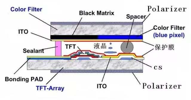
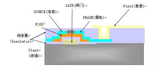
A TFT array is built on the lower glass substrate, the ITO electrode of each pixel is connected to the TFT drain electrode, the gate is connected to the scan bus, and the original source power is connected to the signal bus. When the scanning signal voltage is applied, the original source electrode is turned on to apply the signal voltage to the storage capacitor and charge it, and the signal voltage of the storage capacitor is applied to the liquid crystal pixel in the frame frequency to make it in the strobe state. When addressing again, the signal voltage is used to charge or discharge. In this way, each pixel is isolated by the thin film transistor switching element, which not only prevents cross interference but also ensures that the response speed of the liquid crystal is satisfied with the frame rate speed. At the same time, the gray level can be obtained by the size of the stored information. At present, the gray level can reach 256. Get 16.7 million colors, almost can get full color display. Since the formation of the industry in the 1990s, the production line of thin-film transistor (TFT) liquid crystal displays has developed from the first generation to the sixth generation. The area of ​​the substrate glass has been greatly increased without a replacement, and the output has continued to increase and the cost has continued to decrease. For example, the glass substrate size of the seventh-generation thin-film transistor (TFT) liquid crystal display production line will reach 1870*2200mm. Currently, the LCD TV screen that can be made is 94cm (37inch), and the maximum size of the laptop screen is 38.1cm (15inch). The maximum screen size is 63.5cm (25inch). Another development trend of thin film transistor (TFT) liquid crystal displays is thinner, lighter, and lower power consumption. Based on the development of new materials, the innovation of manufacturing technology, the improvement of equipment accuracy and automation, and the advancement of software technology, the replacement of thin film transistor (TFT) liquid crystal display products is very fast.
The structure and principle of LCD backlight
The classification of the backlight and the structure of the lamp (Lamp)
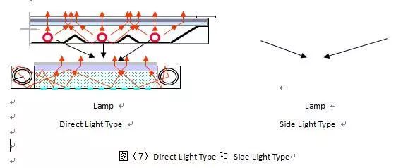
Backlight (hereinafter referred to as B/L) is divided into Direct Light Type and Side Light Type according to the arrangement of the Lamp (tube). The Side Light Type needs to guide the light emitted from the Lamp on the side to the front of the B/L. Light plate, but Direct Light Type is that the light emitted from the Lamp directly emits light to the front of the B/L, so there is no need for a light guide plate.
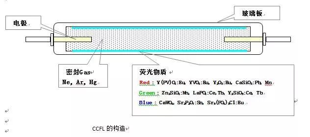
The lamp used in the TFT-LCD B/L light source is a cathode fluorescent lamp (Cathode Fluorescent Lamp), which supplies a certain voltage from the outside, emits electrons on the cathode, and scans the phosphor to create a light source of visible light. The structure of CFL is roughly composed of glass plates, electrodes, sealing gases (Hg, Ar, Ne), and phosphors. CFL scans the ultraviolet rays generated by self-sealing mercury on the phosphor coated on the inner wall of the glass tube to generate visible light. In order to make a small amount of mercury easy to start and to suppress the evaporation of the cathode material, argon is sealed in the glass tube. The types of CFLs are divided into two types, CCFL (Cold Cathode Fluorescent Lamp) and HCFL (Hot Cathode Fluorescent Lamp) according to the mechanism that emits electrons.
1. Lamp: It is a light source that receives high voltage from the Inverter and generates visible light. Mainly use CCFL (Cold Cathode Fluorescent Lamp), and HCFL (Hot Cathode Fluorescent Lamp)
Lamp).
2. Lamp housing: the light source reflected from the Lamp and incident on the light guide plate. Use brass, aluminum, and brass with thin films such as Ag attached to reflectors
3. Light guide Panel (light guide panel): It is mainly made of acrylic (PMMA) by Injection Molding or Casting. It guides the incident light source and has the function of evenly distributing the light source.
4. Reflector: mainly on polyether (PET) equipment to reduce the light source loss incident on the light guide plate, which has a reflection function.
5. Diffuser Down (diffusion sheet): mainly polyether (PET) equipment is made of acrylic resin to form a spherical shape, uniformly diffuse the light source from the light guide plate, and at the same time play the role of light collection.
6. Bottom Prism: It mainly uses acrylic resin on the polyether (PET) equipment to form a prism shape regularly to collect light. The brightness increase rate is 1.55 times that of the user surface.
7. Top Prism: Has the same function as Bottom Prism, increasing the brightness by 1.33 times the surface of Bottom Prism.
Prism is arranged in a cross with each other to collect light sources in the X-axis and Y-axis directions.
8. Diffuser Up (Protector Film): It has the same structure as Diffuser Down, with the main purpose of protecting Prism, also known as protective film. It is necessary to use a transmissive Diffuser, which will cause some light source loss in Top Prism light collection, but it is used to reduce the defects of Prism characteristics.
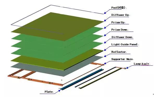
The future of LCD technology
In recent years, OLED, DMD, FED and other non-liquid crystal flat panel displays have been matured in the market. In response to some of the shortcomings of liquid crystal displays, such as low brightness and difficulty in large screens, they have aggressively initiated LCD displays. challenge. As recently, some people have claimed that OLED will replace liquid crystal displays.
In fact, since various displays have different advantages and disadvantages and their respective characteristics, it is generally impossible to replace each other. However, it is completely realistic to use a certain specialty part of itself to replace or impact another type of display device. LCD has to face this challenge and competition. This challenge and competition is not only a threat to the LCD industry, but also a driving force for the development of the LCD industry.
In the future, liquid crystal displays will strive to make major breakthroughs in the following aspects in response to their own shortcomings in coping with the challenges of other types of display devices:
1. Improve the display brightness and contrast by developing reflective displays and improving the backlight, increasing the aperture ratio, and increasing the transmittance of the polarizer.
2. Improve materials, device structure, and technology to increase the response speed of liquid crystal displays. At the same time, efforts will be made to develop some fast-response new liquid crystal display modes, so that liquid crystal displays can more ideally meet the requirements of video display.
3. The narrow operating temperature range is a major defect determined by the liquid crystal material, so it can only be overcome from the liquid crystal material. At present, a liquid crystal material that can work at minus 50 degrees to 90 degrees above zero has been developed. In addition, the development of the auxiliary heating system will also ensure that the operating temperature range of the LCD will be greatly expanded.
4. In order to realize large-screen display, liquid crystal display has opened up a brand-new way-projection display. Based on the original transmissive amorphous silicon TFT projection display, in recent years, it has transitioned to polysilicon TFT projection display. Although polysilicon can increase the aperture ratio by more than 10% to 15%, the display brightness and definition are greatly improved, but it is not ideal. In order to compete with large-screen displays such as PDP, liquid crystal displays have developed a "liquid crystal on silicon" LCOS in recent years. The large-scale integrated circuit is used as the substrate, and the liquid crystal is assembled to form a reflective micro liquid crystal display. A large screen display of 50 inches to 100 inches or more can be realized through the reflective projection of the external light source.
Pv Ribbon Intelligent Factory,Solar Intelligent Workshop,Solar Welding Strip Production,Sunlight Solar Bus Bar Production Machinery
Jiangsu Lanhui Intelligent Equipment Technology Co., Ltd , https://www.lanhuisolar.com