Hyundai's car is about to be launched in the United States. The information that has been released currently mainly includes the overall information of the vehicle, including battery life and power consumption.
➤EPA mileage is 258 miles (415 kilometers)
➤WLTP's mileage is 292 miles (470 km)
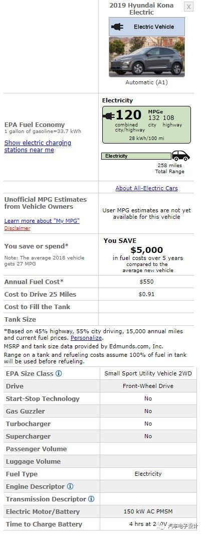
Energy consumption

The parameters and some information about the battery system are gradually released, as shown in the following figure:
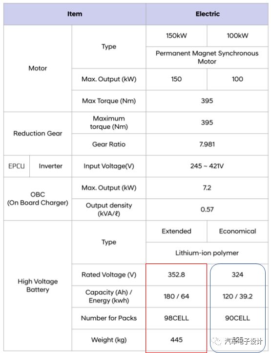
The energy density is actually not high, the low version is around 120, and the high version is around 140.

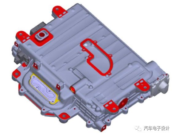
Overview of the entire vehicle drive system

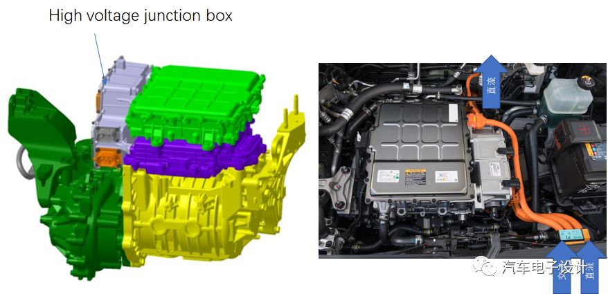
The system integration method is to integrate the front-end components, EPCU, OBC, motor/reducer and power distribution box are all built together
EPCU includes inverter, DCDC and VCU.
Battery system
➤The opening part has been introduced before, and the MSD is retained from the case.
➤Only use a large current input and output interface, the entire high voltage cable is also simplified to a large extent, it can almost be said that it is a point-to-point connection
➤The air conditioning system has a single output, which is simplified for the high-voltage connector of the battery pack
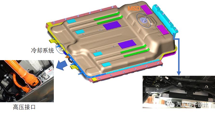
The entire battery pack achieves the balance of internal and external air pressure through 4 PET films (the film is breathable and impermeable to ensure the IP protection level of the battery pack). The PET film is stuck to the outer surface of the upper box by glue. If thermal runaway occurs in the box, the internal air pressure will rise sharply due to the production of gas from the cell monomer, and the PET film will be broken to protect the box.

This simplifies the work of PRA. Take out the quick charge and other contactors, only keep the main positive/main negative, and take out the quick charge contactor through the external series connection mode.
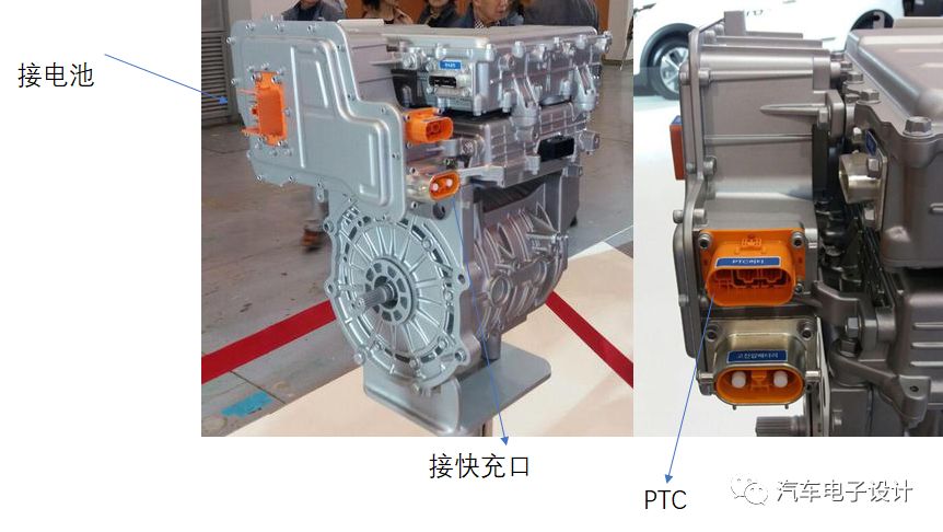
➤The management and control of the connector of the charging part is carried out in the external high-voltage power distribution box.
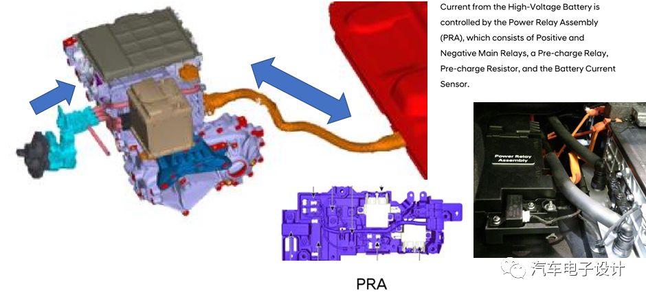
As shown in the figure below, the quick-charging (+/-) contactor group is placed in the high-voltage power distribution box.
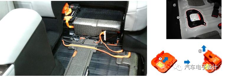
The MSD is placed under the seat, and the MSD can be pulled out through an opening below.

Summary: That's about the existing information.
Storage Water Heater Control Board
Heater Circuit Board,Heater Motherboard,Heater Circuit Board Cost,Carrier Heater Control Board
Full Industrial CO.,ltd. , https://www.iotaindustrial.com