introduction
Construction sites, especially tunnels and underground works, have high requirements for lighting, not only requiring high brightness and reliability, but also ensuring uninterrupted lighting. At present, lighting lamps commonly used in construction sites, such as incandescent lamps, fluorescent lamps, high-pressure sodium lamps, etc., are all powered by the AC grid. Due to the complicated construction site, it is inevitable that power outages will occur. In order to ensure uninterrupted lighting at the construction site, an emergency lighting power source consisting of a rectifier, a battery and an inverter is usually installed. When the grid is normal, the AC power is charged to the battery via the rectifier; when the grid is interrupted, the battery supplies power to the lighting fixture through the inverter. This kind of uninterrupted illumination system is large in size, high in cost, and has to be changed to DC through direct current and DC, so the conversion loss is also large.
In recent years, LED has been rapidly promoted and applied in the field of lighting as an energy-saving, environmentally-friendly, long-life light source. The LED is powered by a DC power supply. The battery is not required to be equipped with an inverter. At the same time, the LED lamp has no stroboscopic power due to the DC constant current supply. At the same power, the luminous intensity is 40% higher than that of the ordinary fluorescent lamp and the high-pressure sodium lamp, and the life is long. Up to 50 000 h, the use of LED lights on the construction site not only saves energy but also ensures the quality of the lighting. In view of the problems existing in the current construction site lighting system, this paper provides a construction site lighting device with small volume, low cost, long life, good power saving effect and high reliability.
1 Construction site LED uninterrupted lighting system
Figure 1 shows the block diagram of the LED uninterrupted lighting system, which consists of a switching power supply, a charging module, a lithium battery, an LED constant current driving module, and an LED lamp. Among them, the main function of the switching power supply is to change the 220V AC power of the power grid into a constant voltage DC power. The DC voltage supplies power to the lithium battery on the one hand, and supplies power to the LED lamp on the other hand. The charging module mainly completes the charging process of the lithium battery; The flow drive module provides a constant current of 1A for the LED lamp. The drive module is powered by the switching power supply when the power grid is normal. Once the power supply is interrupted, the power supply is automatically switched to the lithium battery to realize the uninterrupted illumination of the LED light.

2 Circuit design of LED uninterrupted lighting system in construction site
2.1 Switching Power Module
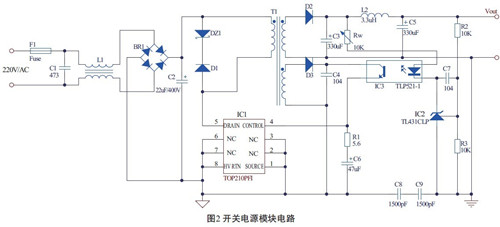
The circuit of the switching power supply module is shown in Figure 2. The 220V AC voltage is filtered by the bridge rectification and capacitor C2 to obtain a DC high voltage of about 310V, which is applied to one end of the primary winding of the switching transformer T1, and the other end of the primary coil is connected to the 5th pin of the PWM switch chip TOP210. TOP210 includes PWM Controller, power MOSFET and various protection circuits. Pin 5 of TOP210 is the drain of internal output MOSFET, and pin 4 is the internal error amplifier and feedback current input pin to adjust the duty cycle of switching power supply. The pin is the source of the internal MOSFET and is the common side of the internal control circuitry. DZ1 and D1 form a clamp circuit that limits the pulse leading edge voltage caused by the leakage inductance of the transformer to a safe value. After the transformer secondary voltage is filtered by D2 and filtered by C3, C5, and L2, the output stable voltage Vout is 9V. The voltage across the feedback coil is rectified by D3. After R1 and C6 are current-limited and filtered, it is applied to the 4 terminal of the control terminal of TOP210. The voltage across C6 is adjusted by TOP210 to stabilize the output voltage. The feedback voltage at the output is determined by the sum of the regulated voltage of the IC2 shunt regulator TL431 of 2.5V, the forward voltage drop of the optocoupler and the voltage drop across the potentiometer Rw. When the output voltage rises, since the voltage across IC2 is always 2.5V, the input current of optocoupler IC3 increases, the equivalent resistance between output transistors c and e decreases, and the diode turns on. The current is increased, the duty ratio is reduced, and the output voltage is lowered to achieve the purpose of voltage regulation.

2.2 Charging module
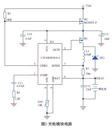
The charging module circuit is shown in Figure 3. The chip LTC4002 is a constant current, constant voltage lithium battery charge controller that uses a current mode buck PWM structure. The LTC4002 internal timer sets the total charge time and charge cycle. When the charge cycle is over, if the battery voltage is still below 4.05V, the new charge cycle will start automatically, and finally each battery float voltage is 4.2V.

The input voltage of the charging module adopts the DC voltage output of the switching power supply module of 9V, and the output charging voltage BAT is 8.4V. The BAT is directly connected to the positive electrode of the lithium battery. The charging current of the charging module is set by the external sense resistor R7 between pin 7 (SENSE pin) and pin 6 (BAT pin) of the LTC4002. At the beginning of the charge cycle, if the battery voltage is lower than the trickle charge threshold (5V), the charger enters the trickle charge mode, ie, trickle charge with 10% of the internally set current full scale; if the battery voltage remains If it is low and exceeds 30 minutes, the battery is considered to be faulty, and the charging cycle is terminated. When the battery voltage exceeds the trickle charge threshold of 5V, the charger enters the full-scale constant current charging mode. In the constant current mode, the charging current IBAT is The external sense resistor R7 and the internal reference voltage are set to 100mV: IBAT = 100mV/R7. In the figure, the NTC (negative temperature coefficient) thermistor is used to detect the battery temperature. When the temperature is lower than 0 ° C or higher than 50 ° C, the charging process will stop.
2.3 LED constant current drive module
The LED constant current drive module circuit is shown in Figure 4. The driver module core is the monolithic switching regulator LM3406, which has an input voltage range of 6 to 42V and can provide up to 1.5A of forward current. It is an ideal constant current driver for LEDs.

When the power supply of the power grid is normal, since the voltage of the Vout terminal is greater than the voltage of the BAT terminal, the diode D4 is in the off state, and the LED constant current driving module is powered by the output of the switching power supply module; when the power supply of the power grid is interrupted, the D4 is turned on, and the LED constant current driving module is turned on. Powered by a lithium battery. In order to ensure that the current of the LED lamp is kept constant, it is necessary to install a radiator with a certain area to reduce the operating temperature of the LED lamp and ensure that the LED life is more than 50 000h.
3 Conclusion
This paper designs an LED uninterrupted emergency lighting system using lithium battery. The system has the characteristics of small size, low cost, long life, good power saving effect and high reliability. It is especially suitable for construction sites such as construction sites. The lithium battery of this system uses 18650 single cells with a capacity of 2 400 mAh. When fully charged, the power can be used for LED lights for more than two hours.
Edit: Cedar
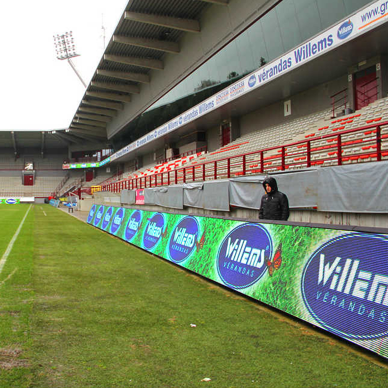
Football Stadium Advertising LED Screen
This series is a classic football field advertising LED Screen, which is specially used for advertising display in various stadiums, such as football fields, basketball courts, badminton courts, tennis courts, volleyball courts and other competitive sports halls. Football Stadium Advertising LED Screen with IP65 waterproof level, excellent anti-collision ability, can resist the impact of balls. High brightnesee makes good perfomance even under sunshine. Good protection design on top of cabinet with thick anti-collision cotton.

Football Stadium Advertising Led Screen,Led Panel Display,Led Video Panel, Football Cup Led Display Billboards
Guangzhou Cheng Wen Photoelectric Technology Co., Ltd. , https://www.leddisplaycw.com