Hou Min Yin Yan Chau 1 1 Lv Xiaojie Wang Zhao Zhidan 2 3
1. State Key Laboratory of Modern Optical Instruments, Zhejiang University, Hangzhou
2. Guizhou Institute of Metrology and Measurement, Guiyang
3. China Institute of Metrology, Beijing
Abstract: The shape and direction of the car's headlights play an important role in the safe driving of cars at night. GB7258 has clear regulations on the relative illumination position of the near and far light shapes and the relationship between them. For manufacturers of automotive lighting, how to adjust the product to the same level requires a cost-effective adjustment device. It is a good method to use the combination of embedded platform and CCD to detect and adjust the shape of the headlamps. The collected image is compared with the standard, and the position difference between the two is verified, thereby adjusting the position of the light shape to be tested to match the standard. The processing results show that the system fully meets the performance requirements of the car front light shape detection. Compared with traditional methods,
This method is more integrated and intelligent.
Keywords: embedded system, automotive headlamp detection, CCD
I. Introduction
Car headlights are mainly used for nighttime driving of cars. Its brightness and direction of illumination are critical to driving safety. When all the headlights of the car are illuminated at the same time, the luminaire should have the performance of the driver to see the traffic obstacles within 100 meters in front. The illumination beam should be directed to the direction of the car, and the direction of the main optical axis should be lower. There are fixed requirements for the direction and relative position of the near and far light (see GB7258 technical requirements).
The headlights have insufficient luminous intensity or the direction of illumination is not suitable. The situation in front of the car cannot be clearly seen, or the driver in the oncoming car is dazzled and obstructs the view. These are the factors that cause the accident.
Based on this, in order to reduce the traffic accident and ensure the safety of driving, the headlights must be adjusted correctly before the car leaves the factory. It is our research goal to adopt new efficient and simple methods to replace the original detection methods. This paper proposes a new method for detecting headlamps from the combined application of CCD and embedded platform.
Second, the system design <br> At present, there are two types of light and dark cut-off lines in the car headlight system, one is a horizontal line and a 15 ° oblique line, and the other is composed of a horizontal line and a 45 ° oblique line. The former is the former. The system structure block diagram is shown in Figure 1.
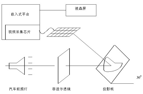
Figure 1 system structure diagram
First, a calibrated headlamp (herein referred to as a standard lamp) can be used to obtain an image of a standard lamp on a built test device, and processed by software to obtain a near-light inflection point and a maximum intensity of the high-beam intensity of the standard lamp or the most The position of the center point of the bright area is used as the standard, and the edge patterns obtained by all the headlights to be tested after software processing are compared with this, so that the position difference between the lamp to be tested and the standard can be obtained. . The processing result is displayed on the LCD screen, and indicates the direction in which the headlights are adjusted. The user further adjusts the lamp to be tested to coincide with the standard according to actual needs.
Third, the embedded platform hardware structure <br> The hardware architecture of the embedded development platform shown in Figure 2 is selected Samsung S3C2410 microprocessor, 64 megabytes of memory and 64 megabytes of NAND FLASH. The video acquisition module uses Phi1ips' programmable video input processing chip (VIP) SAA7111. The software uses Windows CE.net.
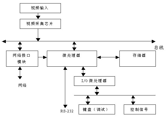
Figure 2 Embedded platform hardware structure block diagram
Fourth, the analysis principle <br> The programming environment used by the software is Embedded Visual C++ based on Windows CE. A pixel point having the largest gradient change is obtained for the obtained low beam image, thereby converting the image into a contour map. The Bresenham line drawing algorithm is used to obtain two straight lines, and the position of the intersection point is obtained in the next step, that is, the position of the low beam inflection point.
After the low beam is adjusted, in principle, the high beam is not allowed to be further adjusted. Therefore, after obtaining the image of the high beam, the maximum or maximum value of the high beam (in general, the maximum value area) is obtained after processing to obtain the maximum value. The center point is used as the center position of the high light intensity, and it is judged whether the relative position of the near and far light meets the requirements.
The software also provides the ability to find the maximum position and description of the light intensity band.
V. Device Flow <br> Figure 3 shows the experimental platform of the system, and Figure 4 shows the workflow of the system. After the low beam adjustment meets the requirements, the system automatically lights up the high beam and turns to the search for the maximum point position of the high beam intensity. The processing result is displayed on the LCD screen.
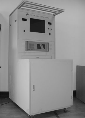
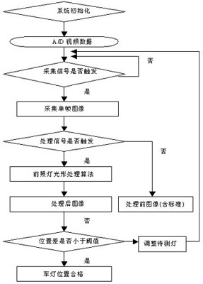
Figure 3 System test device Figure 4 System workflow
Sixth, the analysis of experimental results
Figure 5 shows the actually obtained low beam image, and the green line is the position of the near-light inflection point of the standard lamp. Figure 6 is an image of the lamp to be tested after being processed. The blue line is the light inflection point of the processing result, and is represented by different color areas according to the light intensity level .
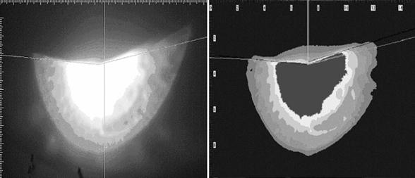
Figure 5 Image to be processed Figure 6 Processed image
Seven, conclusion
From the above experimental results, it can be seen that it is feasible to use a combination of a CCD and an embedded platform to detect a car headlight. The method is simple in device, convenient in operation, and economical and practical. Therefore, it can be considered that the detection method in this experiment has its own superiority, and the market prospect is also considerable.
References [1] Zhang Jun, Li Hanshan. Programmable video signal input processor SAA7111 [J]. Foreign electronic components, 2002, 8:39~42.
[2] Wayne Wolf. Computers as Components: Principles of Embedded Computing System Design [M]. Morgran Kaufmann, 2001: 114-150.
Editor: Chen Dan
Some client may feel that 10th Laptop is little old, so prefer 11th Laptop or 12th laptop. However, you will the 10th cpu is even more powerful than 11th, but price is nearly no difference, especially you take in lot, like 1000pcs. As a professional manufacturing store, you can see Laptop i3 10th generation 8gb ram,i5 laptop 10th generation, intel i7 10th gen laptop, etc. It`s a really tough job selecting a right one on the too many choices. Here are some tips, hope help you do that easier. Firstly, ask yourself what jobs you mainly need this Gaming Laptop to do. Secondly, what special features you care more? Like fingerprint, backlight keyboard, webcam rj45, bigger battery, large screen, video graphics, etc. Finally, ask the budget you plan to buy gaming laptop. Thus you will get the idea which laptop is right one for you.
Except integrated laptop, also have graphic laptop with 2gb or 4gb video graphic, so you can feel freely to contact us anytime and share your basic requirements, like size, cpu, ram, rom, video graphics, quantity,etc. More detailed value information provided in 1-2 working days for you.
10th Laptop,Laptop I3 10th Generation 8gb Ram,I5 Laptop 10th Generation,10th Generation Laptop,Intel I7 10th Gen Laptop
Henan Shuyi Electronics Co., Ltd. , https://www.shuyipcs.com