RFID (Radio Frequency IdentificaTIon) is a non-contact automatic radio frequency identification technology, which automatically recognizes the target object and obtains related data through radio frequency signals. The identification work does not require manual intervention and can work in various harsh environments. This technology has been rapidly developed and widely used since the 1980s. It is a technology that uses radio frequency signals to achieve contactless information transmission through spatial coupling and achieve identification through the transmitted information. As an automatic identification and data collection technology, it has been widely used in the fields of commerce, manufacturing, transportation, logistics management, security inspection, ticket management, military equipment, etc. The application industry continues to expand, and the theory is enriched, developed and improved. Develop into a cross-professional independent field. Many companies have invested in the application and promotion of radio frequency technology to improve operational efficiency and benefits. The US military is the first country to apply RFID technology to military logistics, and has achieved remarkable military benefits in actual combat. RFID technology has gradually become an important technology to improve military logistics supply chain management, reduce support costs, and enhance logistics support capabilities. Tools and means. The main frequency bands currently used by RFID in China are 125 kHz (low frequency), 13.56 MHz (medium and high frequency), 902~928 MHz (ultra high frequency), and more and more research institutions have begun to study the ultra-high frequency (UHF) REID system. Conduct research to realize the characteristics of the system such as long-distance, high-speed, and low-cost.
Because the UHF band electronic tag has the ability to read information at a long distance and dynamically, it has gradually been applied in the fields of parking fees, retail management, public transportation, and automobile security and anti-theft. The antenna is a key component of the RFID tag system. This is because the size of the antenna restricts the development of the miniaturization of the tag, and the wide frequency band of the antenna has practical significance for reducing the cost of the tag. For the needs of low cost and simplified tag structure, the tag chip and the tag antenna are generally directly connected without any matching circuit during this period. This requires the impedance design of the antenna to match the impedance to achieve maximum power transmission. The impedance of the chip is different from the traditional 50 Ω. The typical value is generally a complex impedance with a small real part and a large imaginary part. To match such a complex impedance will narrow the bandwidth of the antenna, so broadband RFID tag antennas have become a hot and difficult point of current research.
This research is based on two modified bent dipole antennas, and the bandwidth of the antenna can be broadened by introducing a suitable feeding structure for feeding at the same time. And based on the simulation analysis of electromagnetic simulation software Ansoft HFSS, a physical antenna was designed and processed. The measured results are in good agreement with the simulation results, which verifies the effectiveness of the design.
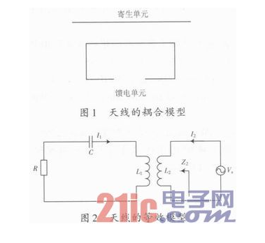
1 Antenna principle and designAccording to the reference, the antenna model can be equivalent to the antenna model shown in Figure 1. When the parasitic element is infinite, the model in Figure 1 can be equivalent to the equivalent circuit model shown in Figure 2.

In Figure 2, the parasitic element is equivalent to L1, R, C of the left loop, where R is equivalent to the self-resistance of the radiator. The feeding unit is equivalent to the right loop, and L2 is equivalent to the self-inductance of the feeding unit. Since the self-impedance of the feeding unit is very small, it is ignored in the equivalent circuit.
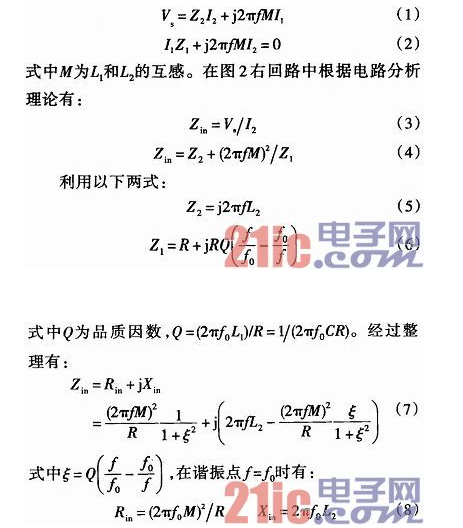
According to the circuit analysis theory of the reference literature, the KVL equation of the loop in Figure 2 can be obtained:

It can be seen from equation (8) that the real part of the impedance in the resonance state is only related to the mutual inductance, while the imaginary part is off with L2. Since the mutual inductance M is related to the coupling distance, the real part of the antenna impedance is related to the distance between the parasitic element and the feeding unit, and the imaginary part is only related to the shape of the feeding unit itself. Therefore, it can be seen that the coupling loading near the resonance point can independently adjust the real and imaginary parts of the antenna.
2 Simulation and test resultsThis article uses Ansoft's electromagnetic simulation software HFSS 11. 0 to simulate the antenna, and the antenna structure is shown in Figure 3. The antenna structure is divided into two parts: a rectangular feed ring and a modified bent dipole radiator. The chip is attached to the opening of the rectangular feed ring for excitation, and energy is sent to the radiator through inductive coupling. The radiator is composed of two modified bent dipoles in which the middle parts are connected together. The lengths of the two bent dipoles are different and not exactly the same. Through unified feeding, two relatively close resonant frequencies can be formed, thereby expanding the bandwidth of the antenna. The stepped bent dipole can shorten the overall length of the antenna, making the antenna structure compact.

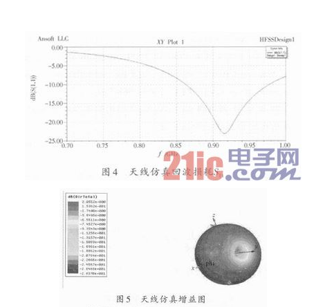
In this paper, the HFSS software of Ansoft and the N5230A vector analyzer of Agilent are used for simulation and actual measurement. Figure 4 is the return loss of the antenna, and Figure 5 is the gain diagram of the antenna. It can be seen from Figure 1 that the working bandwidth of S11<-10 dB, that is, VSWR<2, is 115 MHz, which is between 860 and 975 MHz.


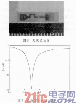
In this paper, a physical antenna is processed on the basis of simulation design, as shown in Figure 6. The dielectric plate of the antenna adopts FR4 substrate with a dielectric constant of 4.4 and a thickness of 2 mm. The measured result is shown in Figure 7.
3 ConclusionThis research proposes a simple structure compatible multi-standard broadband RFID tag antenna. By introducing two modified bent dipoles with slightly different shapes into the antenna structure and feeding them uniformly, two similar resonance points are formed, so that the impedance of the antenna, especially the imaginary part, is in the range of 840 to 956 MHz Keep it stable, and have obtained a good match with the chip impedance in a wider frequency band, thereby broadening the bandwidth of the antenna. It can be known through theoretical analysis that when the antenna resonates, the real and imaginary parts of the antenna impedance can be adjusted separately. Finally, based on simulation analysis, a physical antenna was processed. The actual measurement results are in good agreement with the simulation results, which verifies the effectiveness of the antenna design.
power off protection connector,street light connector,Road Lamp Protection Connector
Guangdong Ojun Technology Co., Ltd. , https://www.ojunconnector.com